 Description: Description:
Multi-channel fiber optic cylindrical connectors have long been the preferred inter-connect solution for military and defense systems. Though ideal for electrical or RF applications, the integration of fiber optic connectivity into military style cylindrical shells have proven challenging and resulted in cylindrical fiber optic connector solutions being more expensive than electrical counter parts.
Cables Plus USA’s new F-LINK™ Inter-connect System embraces proven performance of cylindrical style components, fuses the economic scale of 1.25mm ceramic ferrule technology and incorporates the ingenuity of the Cables Plus USA design team.
Due to maximum flexibility of “provision independent channels”, gender selectable plug or receptacles and total environmental sealing of connector system, the F-LINK™ Inter-Connect System is ideal for almost any application including military, commercial and industrial applications.
F-LINK™ Inter-connect System, also affords a comprehensive family of back shells, assessors, shell sizes, and the first connector system to embrace the emerging trend toward hybrid (the combination of fiber optic and electrical power transmission), within the same cabling sheath.
F-LINK Connector Configurations
 |
 |
 |
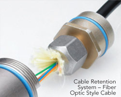
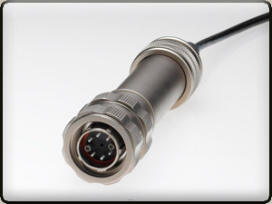
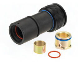
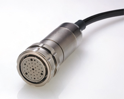
| SS16, Plug, Male w/Backshell, F/O Cable |
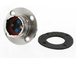
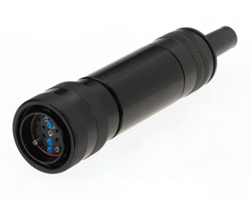
SS16, Panel Mount Receptacle, Male |
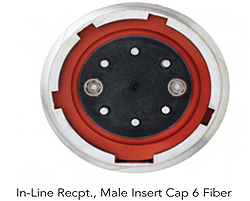
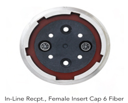
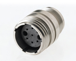
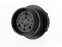
SS16, In-Line Receptacle, Female |
 |
 |
 |
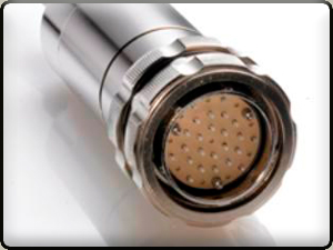
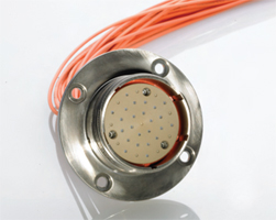
| SS16, Jam-Nut Receptacle, Internal, Female |
SS16, Panel Mount Plug, Female |
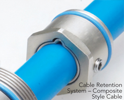
SS16, Backshell for Composite Cable |
 |
 |
 |
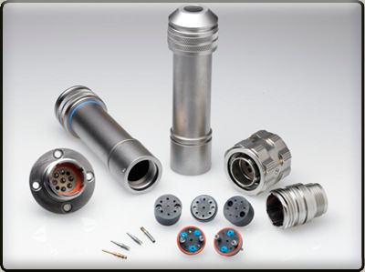
| SS22, Plug, Male w/Backshell, F/O Cable |
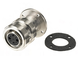
SS22, Jam-Nut Receptacle, Internal, Female |
SS22, Jam-Nut Receptacle, External, Male |
 |
 |
 |
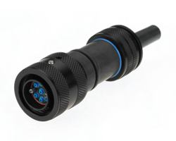
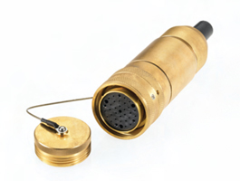
| SS28, Plug, Female w/Backshell, Fiber Optic Cable |
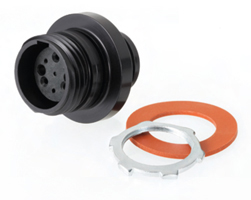
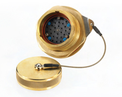
SS28, Plug, Female w/Backshell, F/O Cable, Dust Cap, Brass |
SS28, Panel Mount Receptacle, Female |
Provisioning Guidelines
Fiber Optic Only
- Select the appropriate Shell Size to accommodate the fiber optic channel count.
- Select the connector configurations that meet the intent of the application. Most fiber optic applications require male plugs w/Backshell to support connectivity with female receptacles. Receptacles are selected based on internal, external jam-nut or panel mount options.
- Identify the number of termini required to support the fiber count.
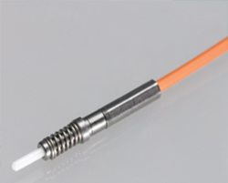
- Apply one crimp sleeve to each terminus when using receptacle configurations without backshells. Receptacles are typically provisioned with simplex 2.0mm loose tube fiber optic cable and simplex connectors (ex: SC, LC, ST, FC) to form pigtails.
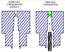
- Specify the hole pattern portion of the final part number by completing the NNNNN portion of each connector configuration (ex: HJVNNNNNNBU00 becomes HJVOOO24bU00 FOR A 24 CH FIBER OPTIC APPLICATION).
HYBRID (Combination of Electrical and Fiber Optic)
- Select the appropriate Shell Size to accommodate the fiber optic and electrical channel count.
- Select the connector configurations that meet the intent of the application. Most hybrid applications require the source of electricity to be protected from hazardous shock along the path of inter-connect. F-LINK supports this requirement through inter-changeable pin/socket insert caps as well as in-line receptacles w/backshell and panel mounted plugs.
- Receptacle options include in-line internal, external jam-nut, in-line or panel mount and can be provisioned as female or male to protect from hazardous shock. Backshells are typically used with in-line receptacles.
- Plug options include standard plug or panel mounted plug provisioned as female or male to protect from hazardous shock. Backshells are typically used with plugs.
- Indentify the number of termini required to support the fiber count.
- Apply one crimp sleeve to each terminus when using receptacle configurations without backshells. Receptacles are typically provisioned with simplex 2.0mm loose tube fiber optic cable and simplex connectors (ex: SC, LC, ST, FC) to form pigtails.
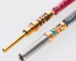
- Identify the number 16#AWG PIN contacts to support male plug or male receptacle configurations.
- Identify the number of 16#AWG SOCKET contacts to support female plug or female receptacle configurations.
- For applications greater than 16#AWG, larger gauge wire can be support by splitting stranded wire between tow 16#AWG contacts or with custom F-LINK applications using 10#AWG contacts. Contact your sales person for additional information.
- For applications that require ground fault detection, a long pin (UV165016AA) is applied to the center hole of the male insert body making first contact with the mating socket (also located in the center hole), prior to full connector engagement.
- Specify the final part number by completing the NNNNN portion of each connector configuration (ex: HJVNNNNNB100 becomes HJV20324B100 for a 3 electrical + 24 fiber optic with long ground pin).
Plating Options
All F-LINK configurations are supplied with BLACK ANODIZE as standard plating. Additional plating options are available by designating the 9th digit of the part number (ex: HDUNNNNNBU00) with a choice of plating/alternate materials as listed:
- "A" Electroless Nickel Plating, Mil-C-26074, 3mil(±0.5mil)
- "B" Black Anodize, Mil-A-8625 TYPE 2 CLASS 2
- "D" 303 Stainless Steel, Passivation per QQ-P-35/ASTMA967
- "E" 316 Stainless Steel, Passivation per QQ-P-35/ASTMA967
- "G" Naval Brass, C 46400 H02 Half Hard ASTMB 21/B21M
Keying Options: All F-LINK plug/receptacles are supplied KEY 1 mechanical key options. Alternate keying options are available upon request.
|